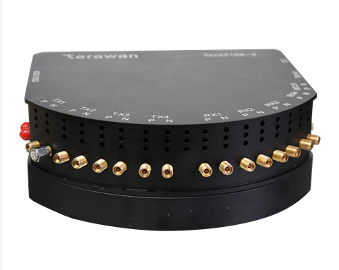
The Tera2100-2 is 10G/25G/40G/100G Berts system, could provide 10G/25G/40G/100G optical module test/debug solution for R&D engineer and manufacture. the 40G/100G port support QSFP+/QSFP28 form factor; 4 Pair RF port could support both bit rate setting: 10.3125Gb/s, 11.3Gb/s, 14Gb/s(16G FC), 24.33G/s(CPRI10), 25.78125Gb/s and 28Gb/s(32G FC).
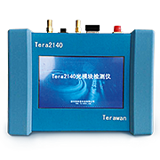
The Tera2140 could support transceiver DDM function and check the module live status. And pattern generator and BER error checker, which could work individual support 10G/25G/40G/100G test.
? 9V power supply, could support remote control in lab.
? Support different PRBS pattern, include PRBS7/PRBS15/PRBS31
? Could parallel test two port:10G and 40G, 10G and 100G, 25G and 40G, 25G and 100G
? Support realtime BER report for both port
? Support Error bit insertion function for troubleshooting
? Support Alarm-history function, record alarm history at long-term testing
? Both port have trig clock output for the eye diagram monitor.
Power supply
Tera2140 adapter 9V DC power supply. Power supply must not exceed 9V, higher than 9V will damage the analyzer permanently.
Console Interface
Tera2140 use the COM for the remote control and test function.
Traffic Interface
Tera2140 have two transceiver port:
1st port is 40G/100G port, support 40G QSFP+ module function and performance test and 100G QSFP28 module function and performance.
2nd 4pair RF port is 9~30G port.
|
Parameter |
Min |
Typical |
Max |
Unit |
備注 |
|
Data Rate |
9 |
|
30 |
Gb/s |
|
|
Output Amplitude |
200 |
|
1000 |
mV |
|
|
Jitter(P-P) |
|
5 |
|
Ps |
PRBS31 |
|
Jitter(RMS) |
|
900 |
|
fs |
PRBS31 |
|
Rising/Fall time |
|
|
12 |
Ps |
|
|
Pre-emp |
|
|
4 |
dB |
|
|
Input amplitude |
20 |
|
1000 |
mV |
|
|
Input Jitter tolerance |
|
0.5 |
|
UI |
均衡最優(yōu) |
|
Input equalization |
|
|
12 |
dB |
|
|
Power supply |
5 |
8.5 |
9 |
V(DC) |
|
|
Power dissipation |
|
|
15 |
W |
|
|
Operation Temp |
-5 |
|
55 |
oC |
|
|
Storage temp |
-10 |
|
70 |
oC |
|
|
Humility |
5 |
|
90 |
% |
Non-Condensing |
|
RF interface |
K(2.92mm),Compliant SMA |
|
|||
Trigger Clock Interface
Tera2140 have two trigger clock for the both transceiver port:
1st trigger clock is for 10G/25G port, support 10G SFP+ and 25G SFP28 module eye diagram test
2nd trigger clock is for 40G/100G port, support 40G QSFP+ and 100G QSFP28 module eye diagram test
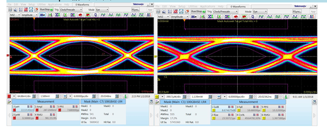
28.1Gbps output eye diagram

2100-2 RF port output eye 2100-2 optical port eye
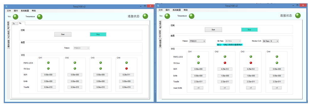
GUI:
The BERT system could be control by computer,RF BERT and optical BERT system GUI as following


